Vintage ex-Yugoslav fuse box
This page documents an old fuse box from Slovenia, formerly part of Yugoslavia, which has been taken out of service in 2025 and replaced with a modern DIN rail breaker box.
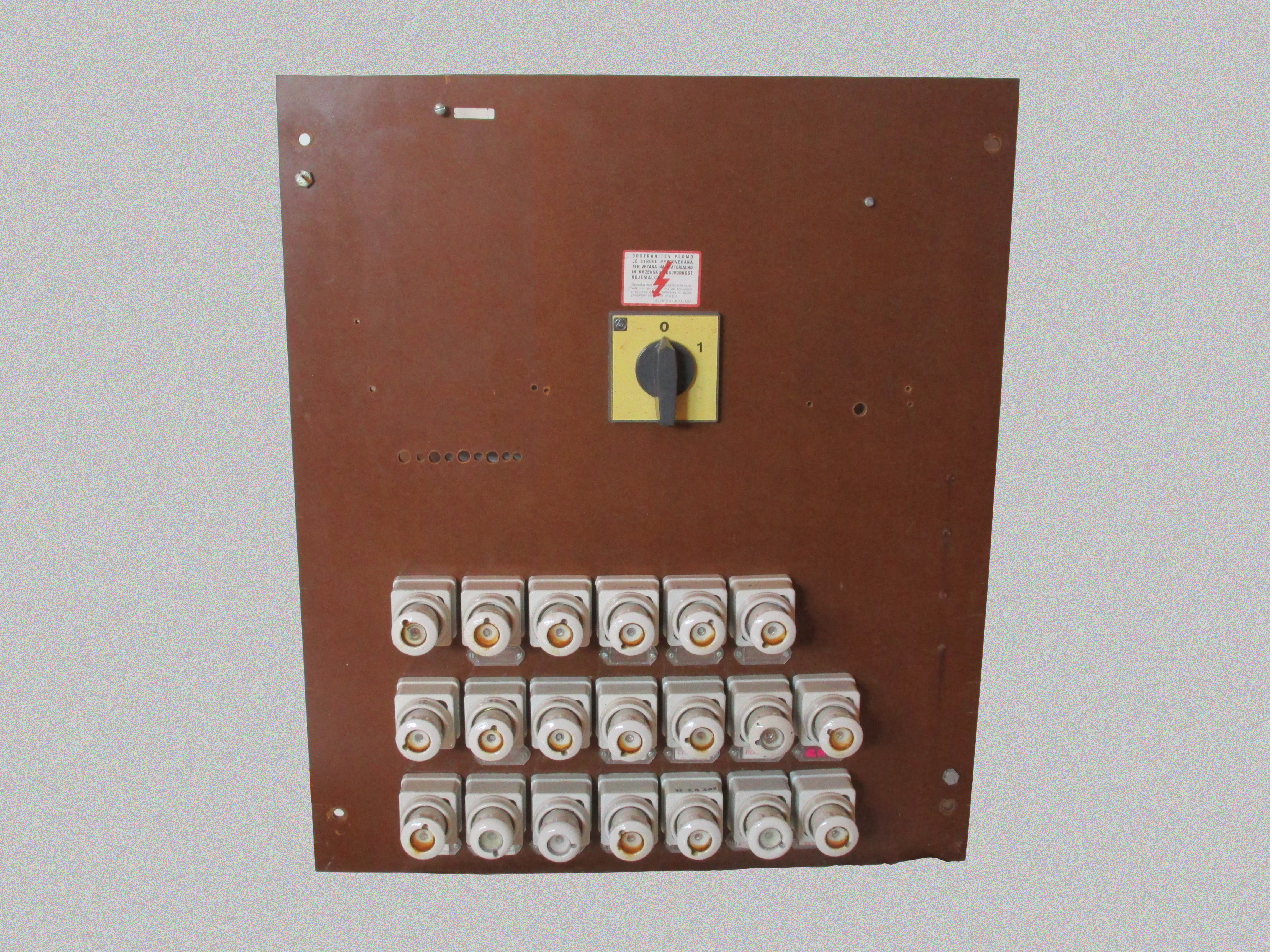
The fuse box follows a design practice once common in many countries, even outside of Europe, of using many individual items all mounted to a large board. The board itself is quite thick, around 0.7cm, and is made out of some sort of smooth material. To it are mounted 20 Diazed fuse holders and a large rotary power switch.
To the left of the main switch a space is present for the power meter, while to the right there's space for another device, both of which have unfortunately been removed.
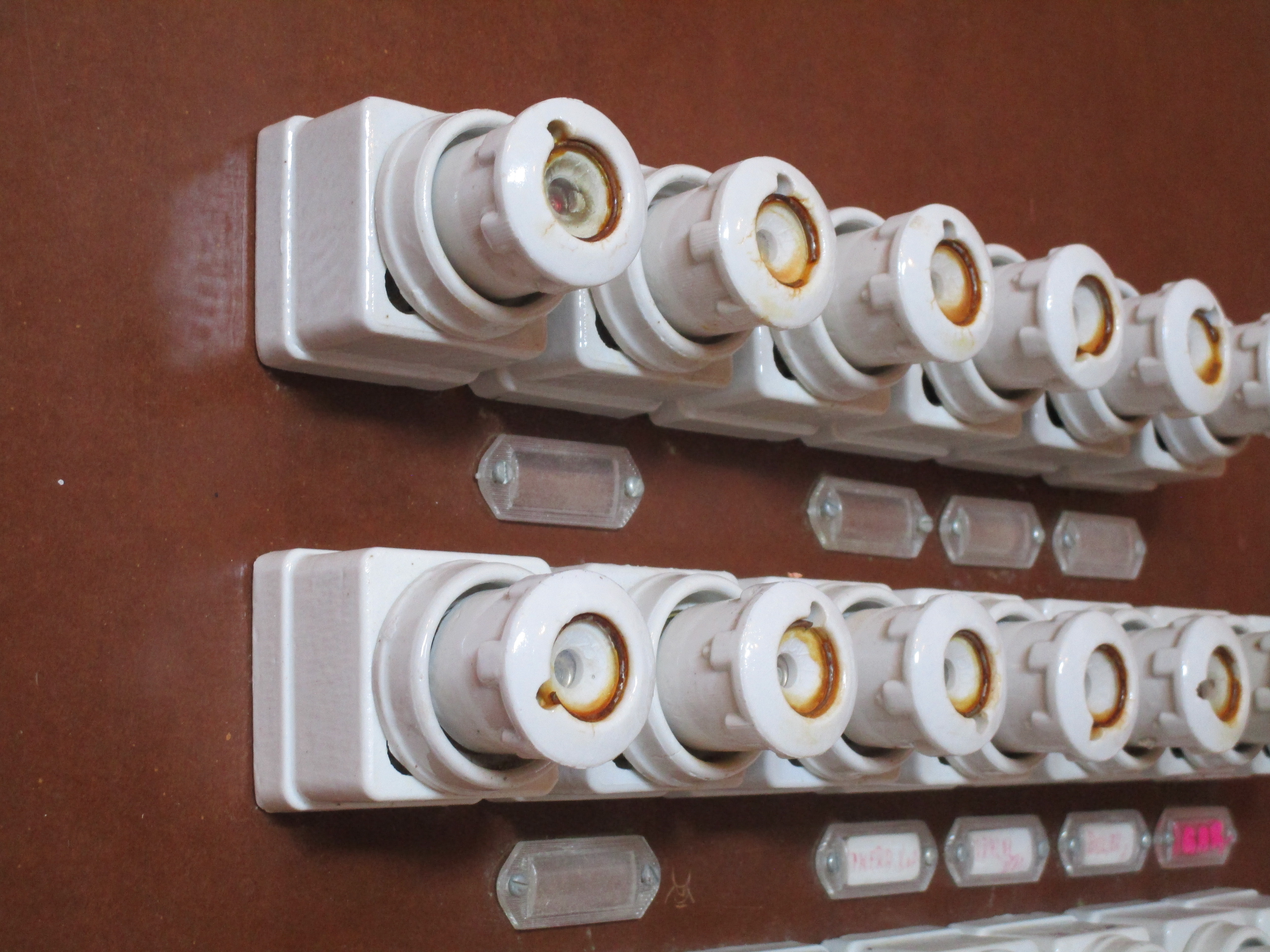
Each circuit has a small plastic label holder below it, inside which a small piece of paper can be inserted to indicate its function, though many of the labels are missing. While most of the circuits are single phase, there are also two three-phase ones which thus have three fuses per circuit, with a single label underneath.
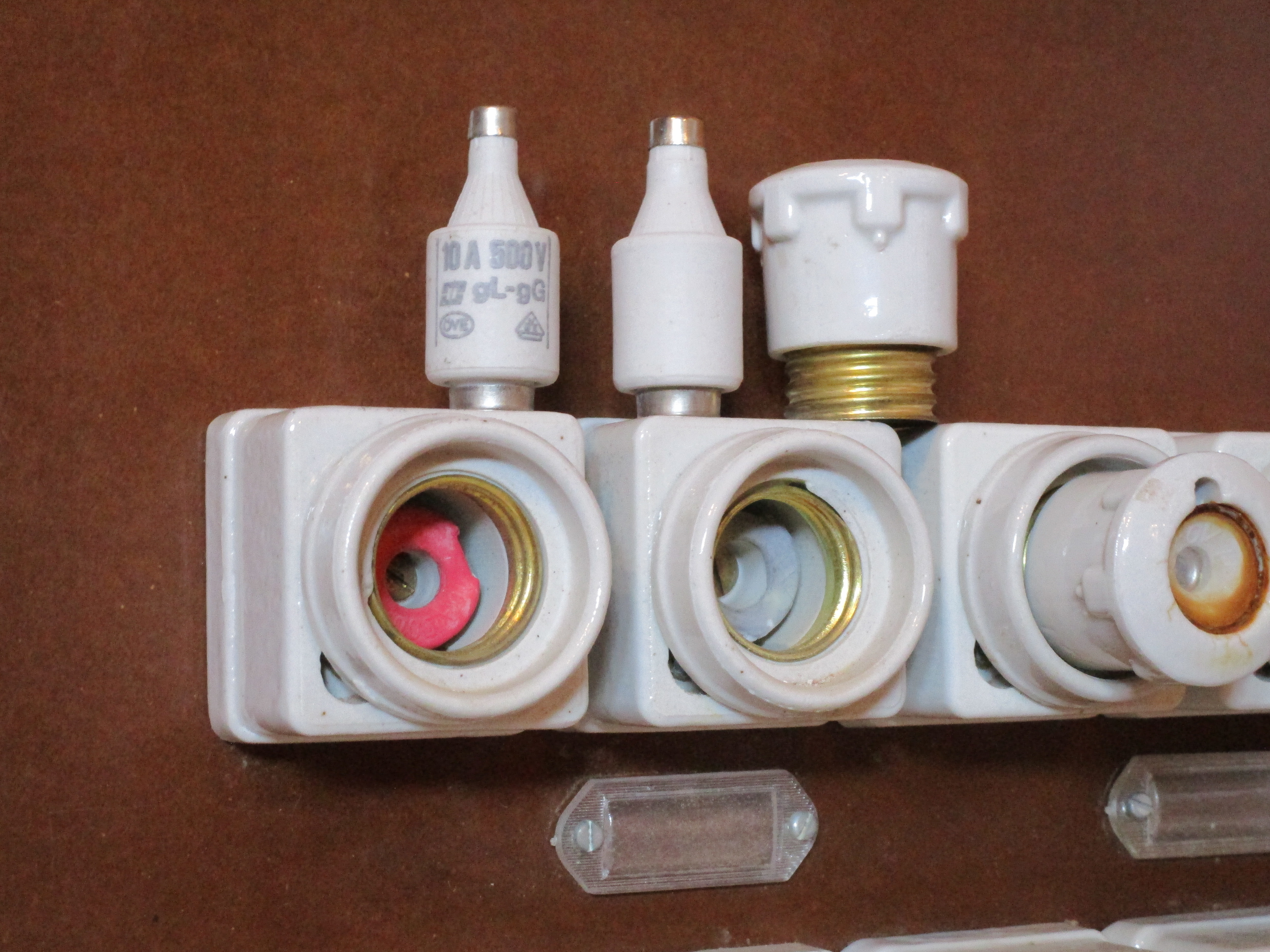
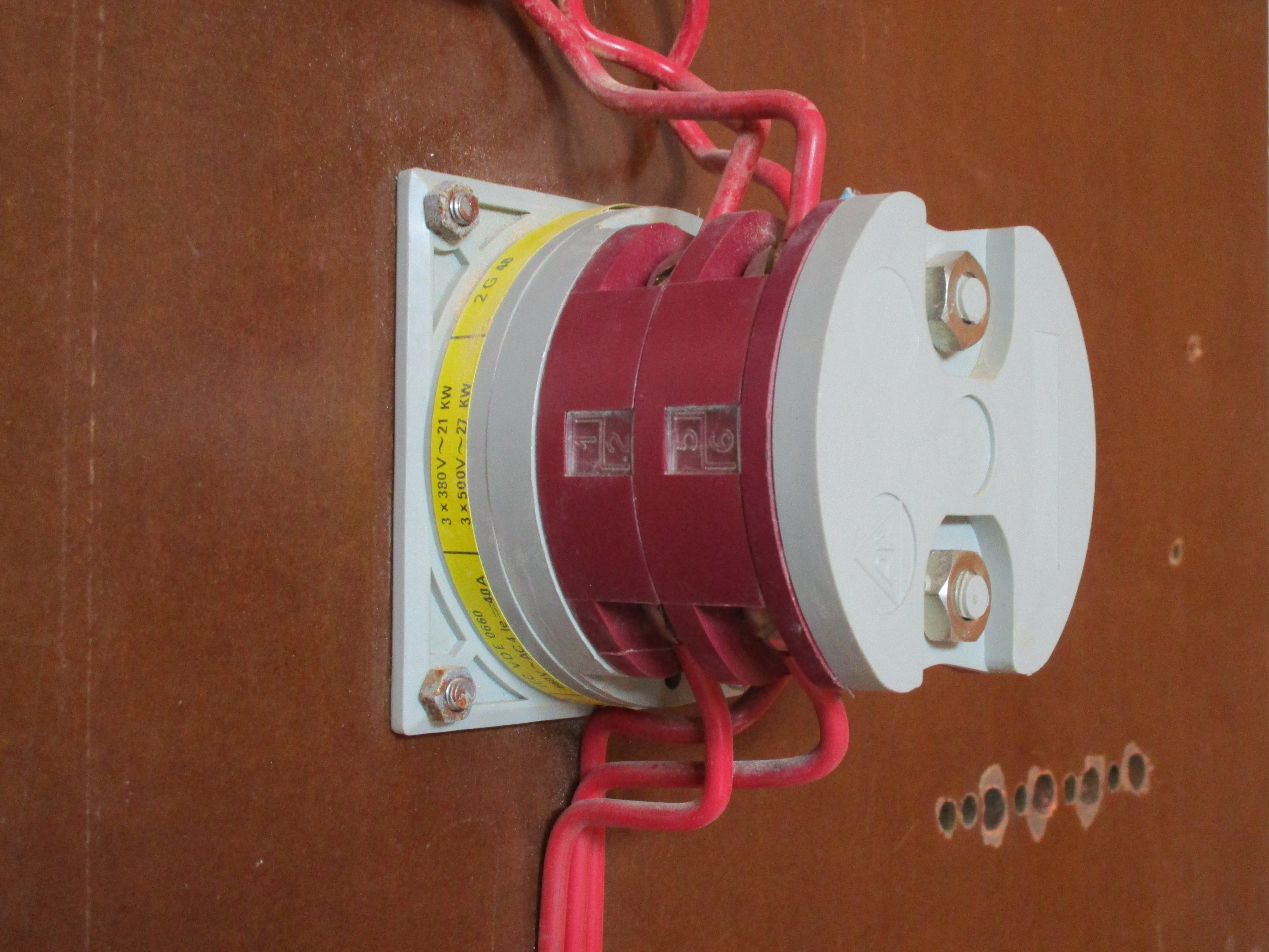
The fuses are of the Diazed DII type that was common in the vast majority of European countries at the time. The fuse, shaped like a bottle, is housed in a cap which then screws into the fuse holder. A coloured gauge ring prevents the insertion of a fuse of a higher rating. In this case all the circuits are either 10A (red) or 16A (grey). While it was certainly an option, none of the fuses have been replaced with circuit breakers.
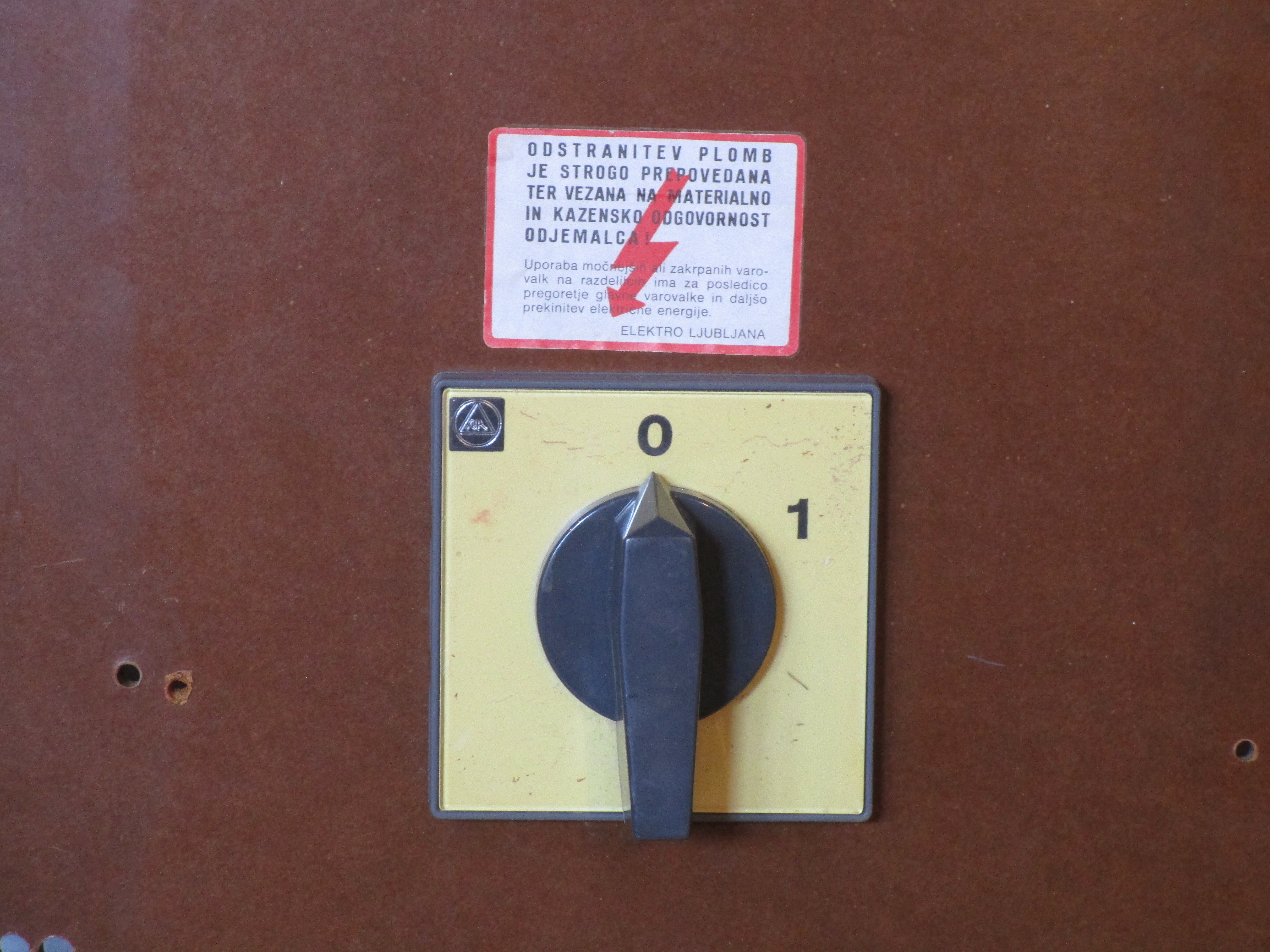
The large rotary power switch on top disconnects all three phases (not the neutral) when in the upwards
position. It's rated for 40A and was built by Rade Končar in Zagreb. Above it a label is present, stating:
Removal of the seals is strictly prohibited and bound to material and criminal liability of the subscriber. The use of more powerful or patched fuses leads to tripping the main breaker and lengthier interruption of electrical energy. ELEKTRO LJUBLJANA
As the meter was placed directly on the fuse board, the whole panel was designed not to be opened by unauthorised persons, to prevent someone from tampering with the incoming supply wires feeding the meter and stealing electricity. This was accomplished by holding the board in place using special screws which could only be removed by cutting off lead seals from the power company - the ones mentioned in the warning label, and similar to ones ordinarily found on power meters. Naturally this also made it harder for an ordinary person to add or modify a circuit.
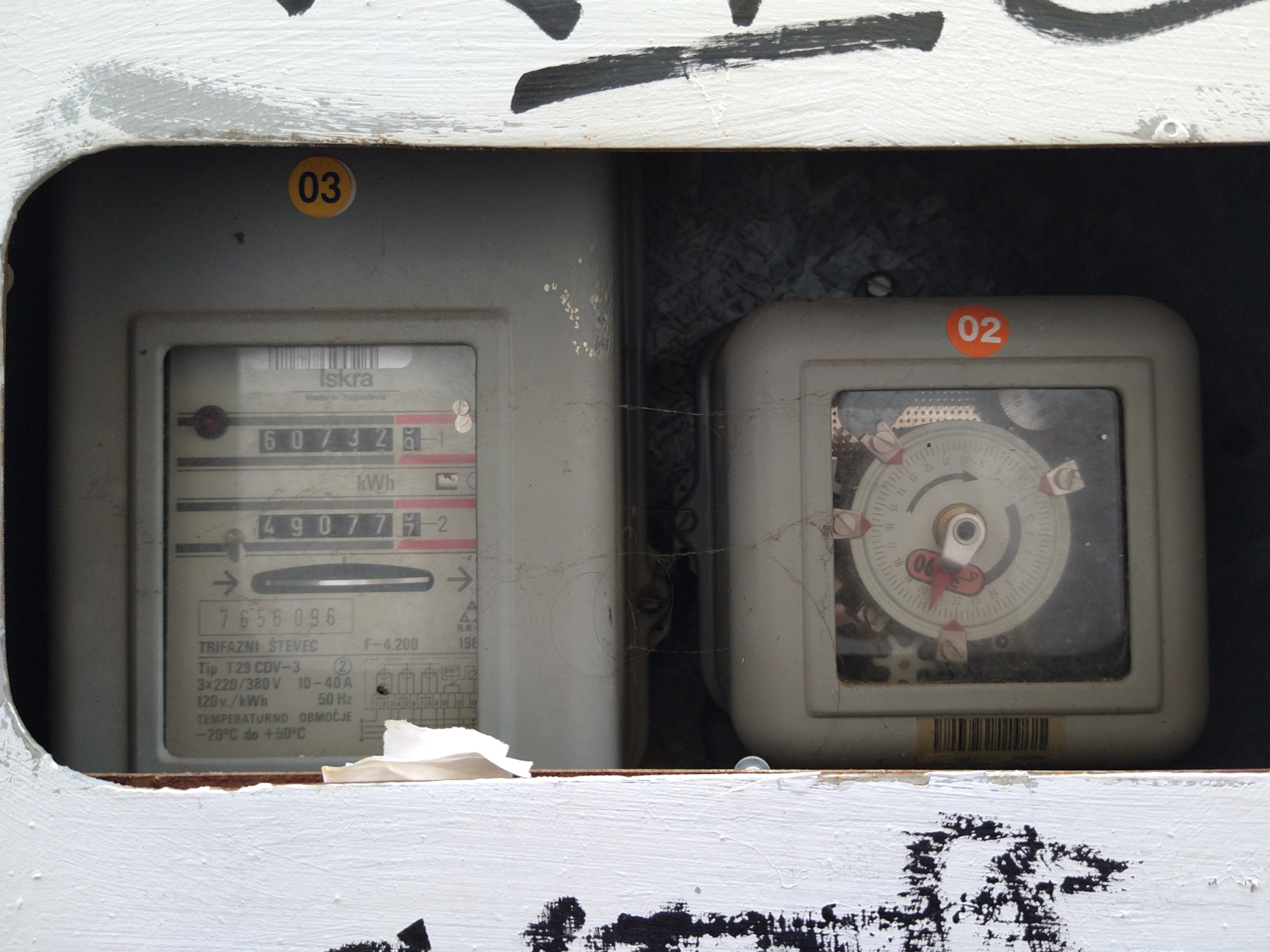
Both the power meter and the second device to the right are no longer present, so we can't know for sure what the latter would've been. However, it's likely that it would've been a time switch, a special clock for controlling time-based variable power rates, indicated by a second register on the power meter that could be switched to by powering an additional terminal - a hole for which can still be seen on the board. The third photo below shows such a setup outside of a building in Koper, Slovenia, with a three-phase Iskra meter with dual registers and a matching time switch.
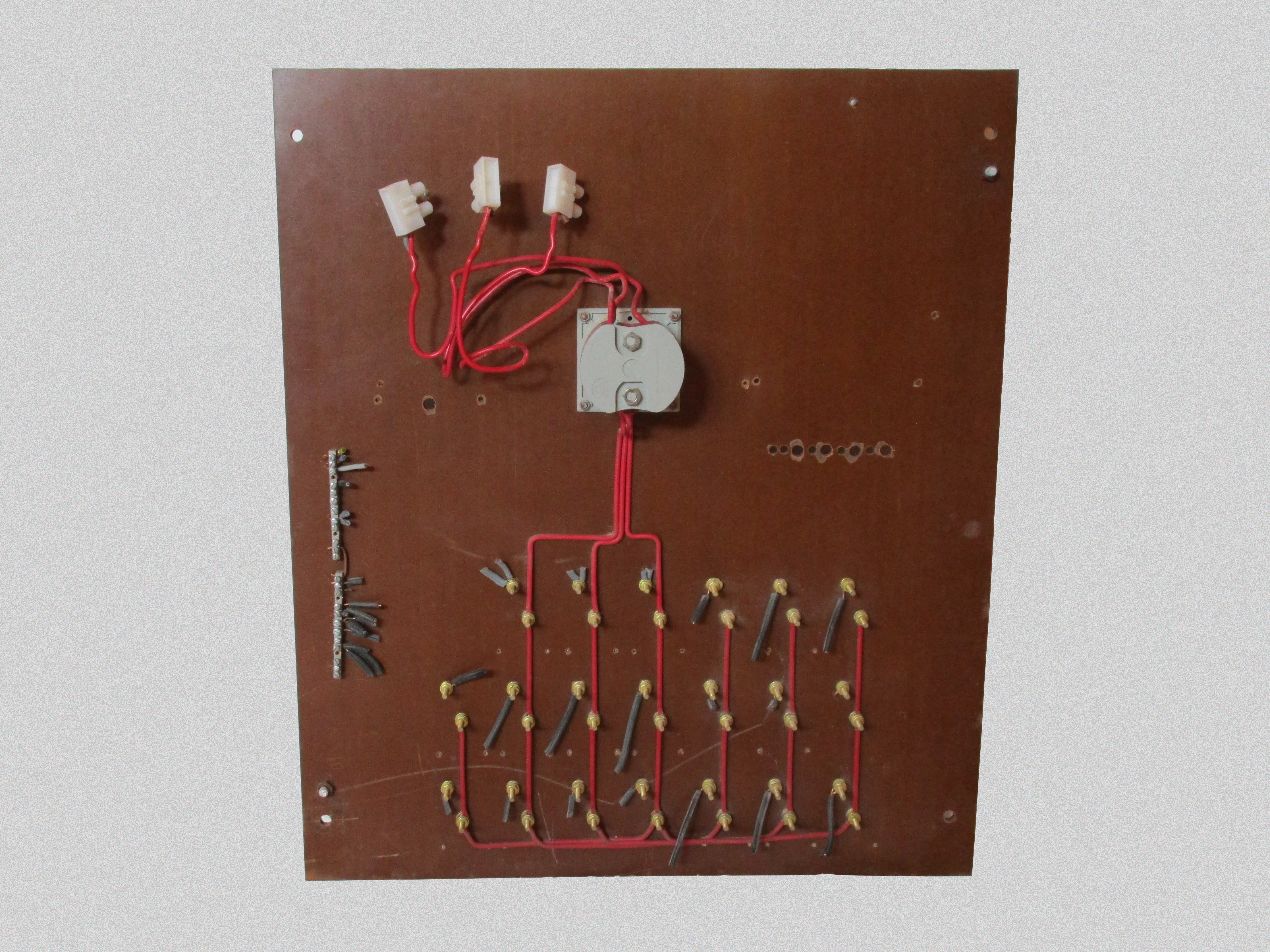
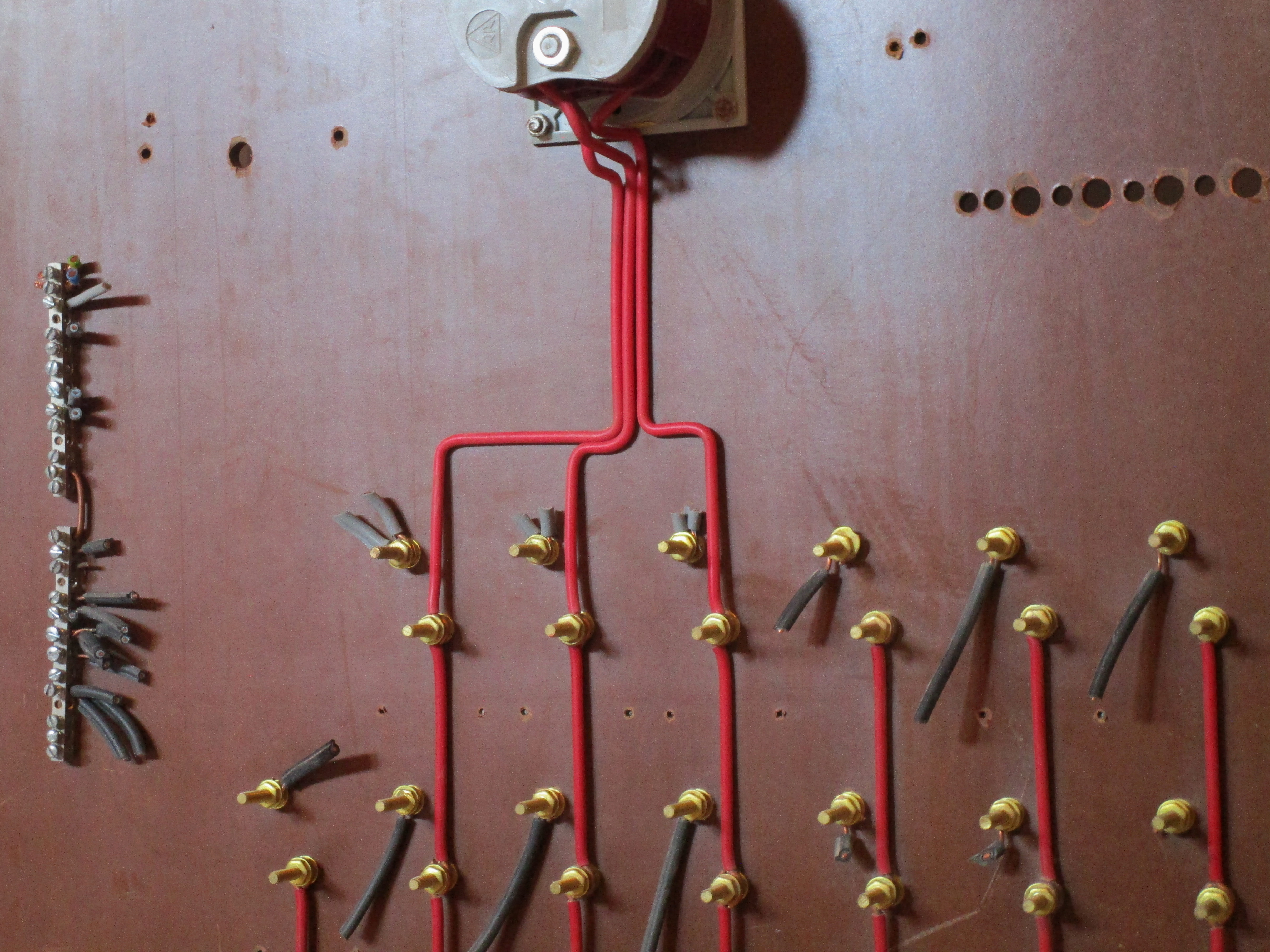
The rear of the fuse box features an intricate and clearly well-thought out layout using pieces of solid-core wire carefully measured, cut and bent to connect all the various individual fuse holders to the main switch. Each fuse holder is held with two long screws, which double as crude wire terminals. The red distribution wires, one per phase, run between them and are held with a nut and washer.
The input side of the main switch is connected to similar red wires, though without the careful wiring arrangement. At the end of these wires there are three white "choc-block" terminals, presumably a modification from an earlier relocation of the power meter. The main fuses or breakers for protection of the incoming supply were once housed in a separate cabinet inside the house, also sealed, and later moved elsewhere.
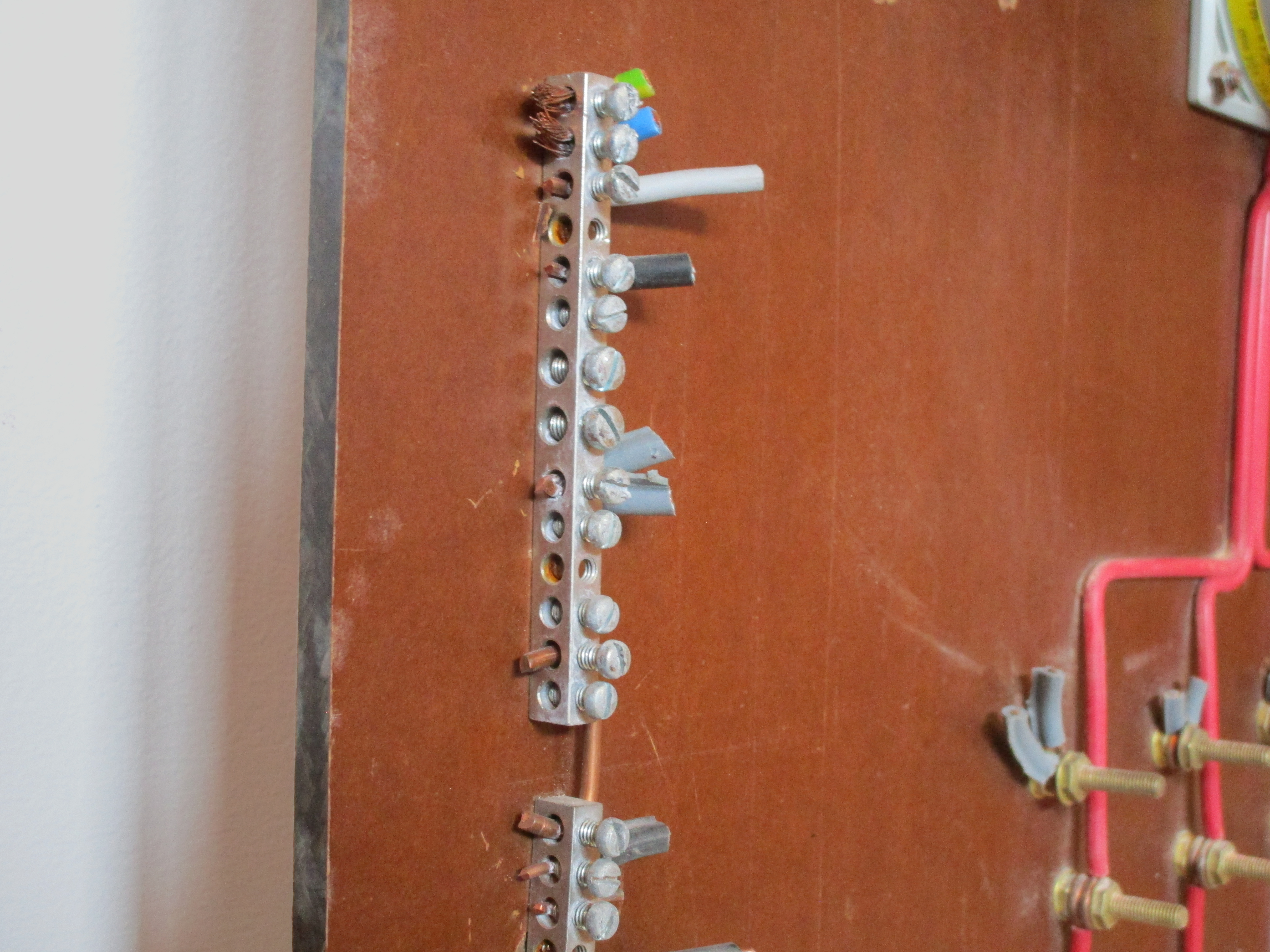
To the left of the board two terminal bars are present for the neutral, linked together with a small
length of wire. There's no separate earth bar: most circuits in this house either had no earth whatsoever or
were wired with the TN-C system, where the socket had a link
between the neutral and earth terminals.
On the top, two more modern stranded-core wires are present, likely from a later modification, a blue one
presumably for the incoming neutral connection and a green-yellow one for the earth. Assuming the earth wire
was for an earth rod or electrode, this makes sense as a way to keep the neutral - or, more accurately, PEN
- wire closer to earth potential.
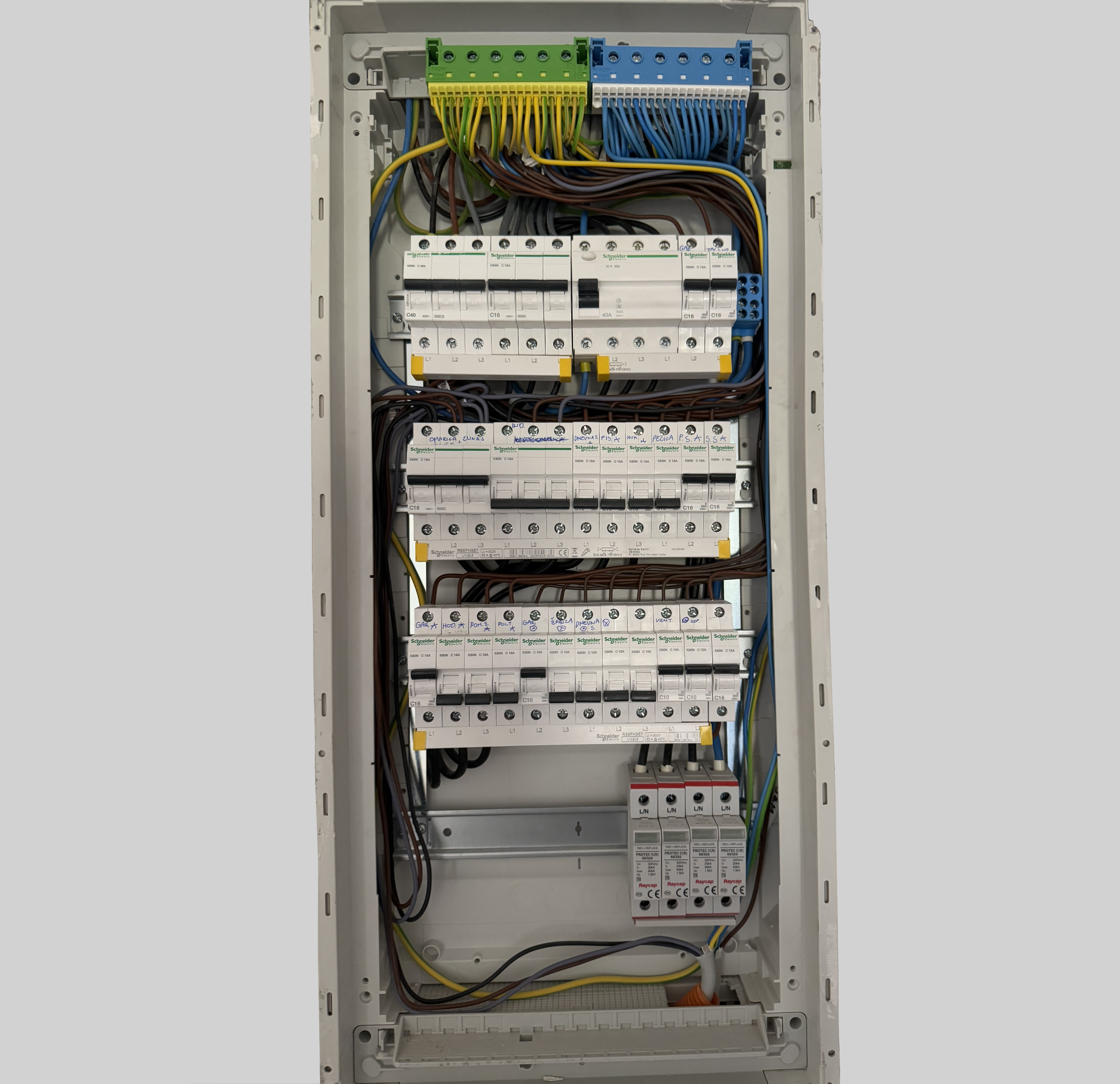
Modern breaker box
A brief look at the breaker box that replaced the old fuse panel: it's housed in a 4-row enclosure by Hager, with breakers by Schneider Electric. As required nowadays, all of the circuits are protected by an RCD except for one feeding a secondary fusebox. Busbars distribute all three phases to the breakers, alternating between L1, L2 and L3. A small DIN-mounted terminal block distributes the incoming neutral to the RCD and subpanel. Additionally, as is common in modern electrical panels in Europe nowadays, a surge protector device (SPD) is present.
The circuits have been rewired and thus now feature standardised wire colours and proper earthing (TN-C-S system). Thus, on the top of the breaker box we can see two terminal blocks for the earth and neutral. Such terminal bars are modular, as they're available in several different sizes and are clipped in dedicated spaces present on the top and bottom of the enclosure, allowing for flexibility according to the needs of the installation. Regular circuits are wired with push-in connections, while a few screw terminals remain present for thicker stranded-core conductors.